Project Overview - GitHub
I am a co-author of this project, and my partner is owed as much credit as I am for the way this project came together.
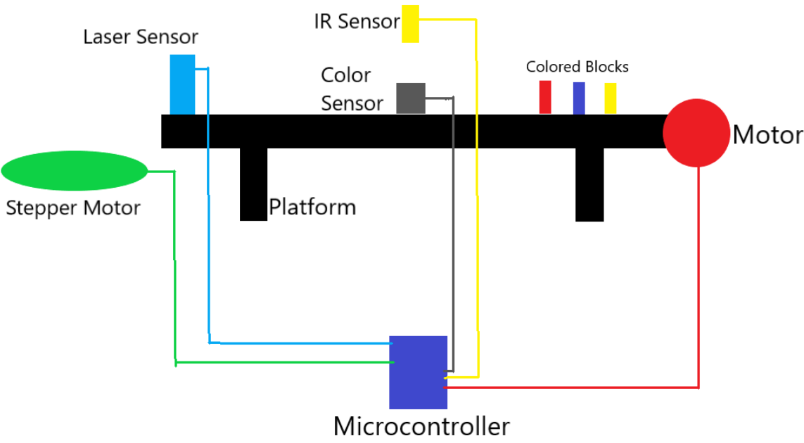
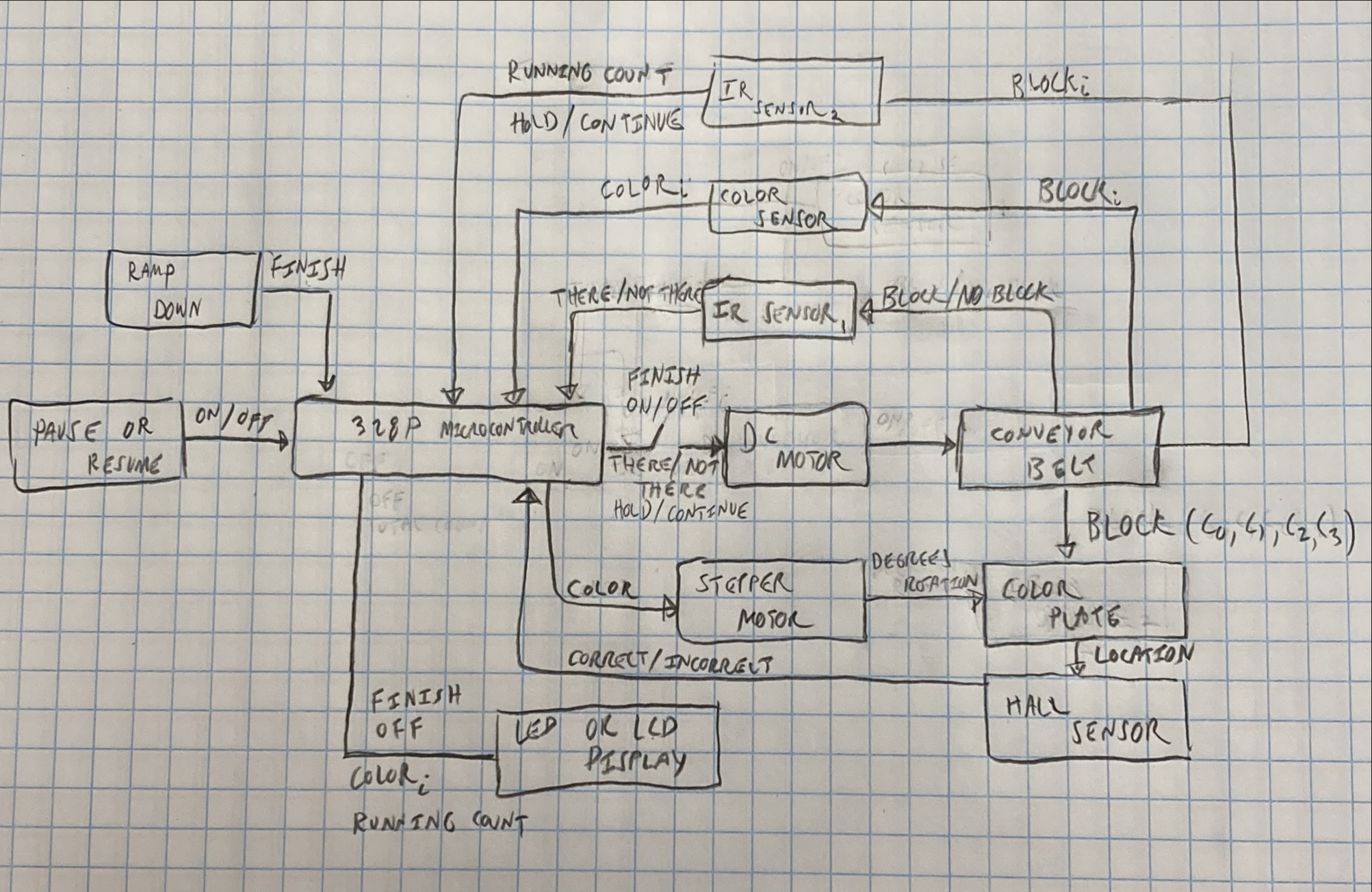
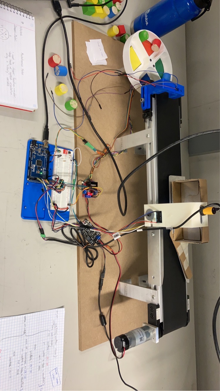
This project is characterized by a conveyor belt that automatically sorts colored blocks. When unsorted colored blocks are input, the system will output sorted colored blocks. The videos above provide a clear illustration of the system's function. The remainder of this page is populated with fragments related to the engineering that went into this project.
Arduino Overview
A high-level description of an Arduino board can be reduced to a microcontroller (MCU) and a printed circuit board (PCB), emphasizing the MCU as the essential tool and the PCB as its interfacing environment. The ATmel ATmega 328P (328P) MCU plus an Arduino PCB submit the Arduino Uno to this description. Interaction with the 328P is facilitated by the PCB it sits on, however, plenty of users elect to interface with these chips using a Custom PCB or even just a breadboard.
MCU instructions are typically programmed in C or C++ using an Integrated Development Environment (IDE), like Atmel's Microchip Studio. Other languages and IDE's like Assembly or Python and Visual Studio or Arduino IDE can be used. The applications presented here are written mostly in C using Microchip Studio.
These instruction files (scripts) are compiled, or translated, into files an MCU can understand, called hex (hexadecimal) files, and uploaded to the MCU from a computer. Instructions given to an MCU often map a system of inputs to program logic which maps a system of outputs back through the PCB for some function, like controlling an LED.
Essentials
There are a number of fundamental concepts and components essential for interaction with Arduino boards. The following is a very brief description of those most universal to the successful marriage of software and hardware.
- Binary (logic) signals: a digital signal that can either be high or low, corresponding to a 1 or 0 in logic terms and 5 or 0 volts (usually) in physical terms.
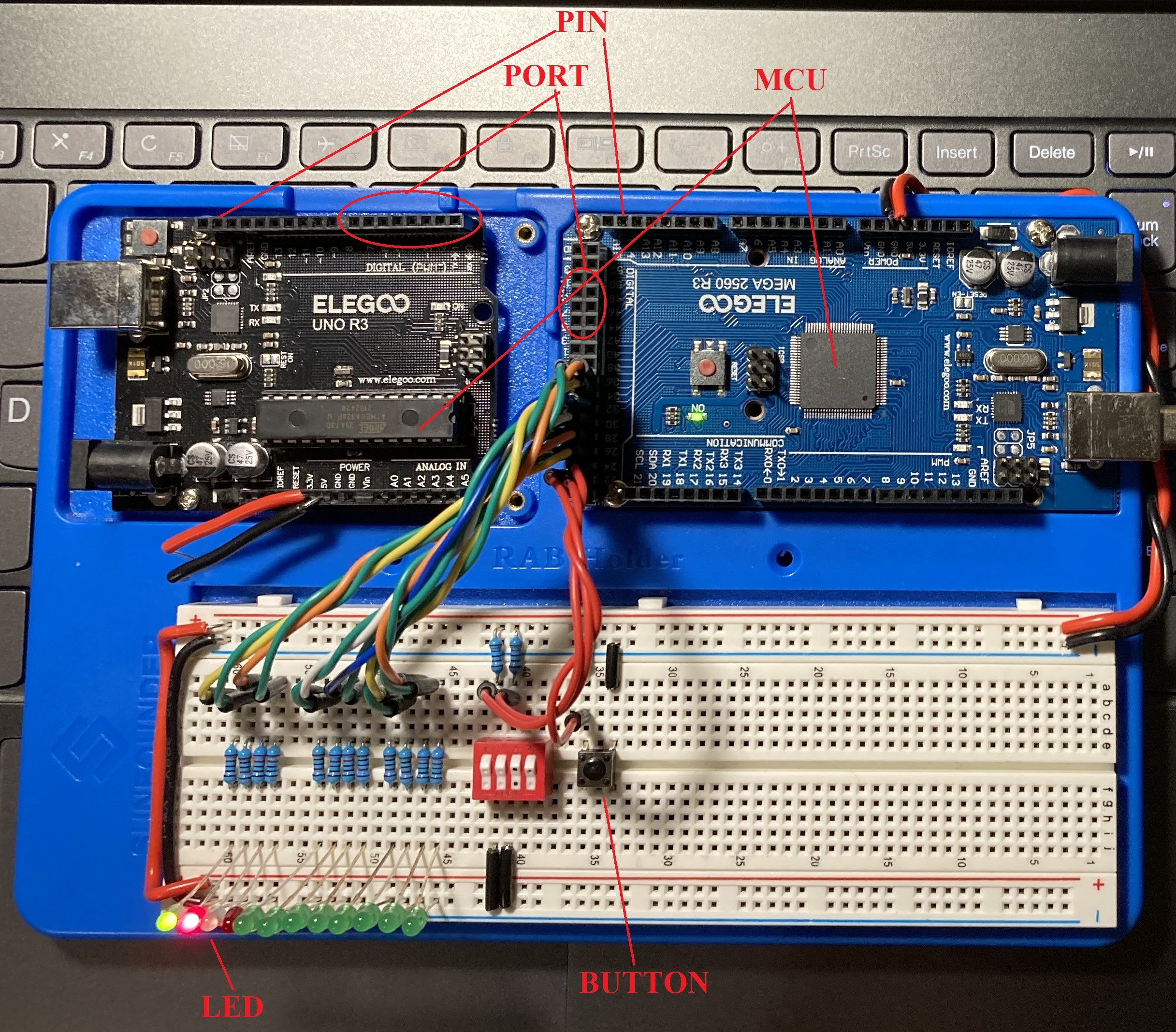
- Pins and ports: a pin is an electrical lead on the MCU that is connected to the PCB, also called a bit. They are organized in bunches, called ports, and can send or receive signals to or from a given system, respectively.
- Registers: a register occupies a space in memory that data can be read from or written to. Data read from registers often represent system inputs, while data written to them represent outputs. A port is a type of register.
- Special function registers (SFR): SFR's are similar to a traditional register, except they have special bits called control and flag bits. Writing to a control bit toggles native MCU functions, while reading from a flag bit typically indicates some status regarding a triggering condition in the MCU. These register functions ship with the chip as opposed to plain registers which inherit functionality from instruction logic.
A real synthesis of these basic elements can be illustrated by an Arduino and a mechanical push button used to light up an LED. Pressing the button completes a circuit that sends a 5 volt (high) signal to a pin connected to one end. The unpressed case sends the same 5 volt signal to ground and a low signal to the pin. Software instructs the MCU to read the signal from the memory address register (MAR) corresponding to the input pin and submit the binary signal to program logic. The logic maps the input to an output, responding through a different pin using its unique MAR. The output pin sends a 5 or 0 volt signal to the LED circuit, either turning it on or off depending on the MCU's instructions.
Configuration
The Arduino Mega 2560 is comprised of an Atmel ATmega 2560 (2560) microprocessor and Arduino board. The microprocessor's datasheet and Arduino board pinout are used for the marriage of software and hardware. Remaining site content is confined to applications using this microcontroller and board but can be replicated in others following the same principles.